Basics of the Acoustic Phonograph
This page gives a brief overview of the operation of the acoustic
and electric phonograph. Readers who are new to this hobby are encouraged to consult some of the
books listed in the Resources section for complete information on the
workings of acoustic phonographs. This brief section is mainly intended to show the
function of the basic phonograph system and to establish some of the terminology that
is used in many of the articles on this website.
All Victor machines of the acoustic era were based on the Berliner flat disc design (see the discussion on records for more information). These discs revolved at 78 RPM and used the "lateral cut" (side-to-side) recording method. Some other manufacturers, including Edison, used cylinders (and eventually discs) with a "vertical cut" system, wherein the needle moved up and down to reproduce the acoustic signal (see diagram at right). The vertical cut system was often called the "hill and dale" method; it worked well, except that it required an additional lead screw system to move the soundbox and stylus along the record; the grooves themselves could not be used to "pull" the needle along as the record played. This added complexity eventually doomed the vertical cut method to obscurity, as it added both cost and complexity to the playback system.
Only the lateral cut method will be discussed in these articles, although many of the same design elements are common to both methods. As the needle tracks the lateral grooves, vibration is mechanically coupled into the soundbox, which consists of a thin diaphragm of mica or (later) aluminum. The diaphragm vibrates in sympathy to the needle movement, and provides a large surface area to subsequently vibrate the air molecules within a hollow tonearm. Thus, mechanical energy is converted into acoustic energy. The air molecule vibration "chain reaction" within the tonearm causes a soundwave to move through the tonearm and into the horn, which directs it into the listening environment. See detailed description below.
Prior to the use of spring motors, the
first phonographs required the user to continuously rotate a crank as the record
was being played, but this was quickly deemed impractical as most users didn't
want to spend their evenings constantly turning a crank through every record.
After 1901, a spring-powered motor was utilized to spin the turntable on most
Victor machines, which required the listener
to simply crank-up the machine once before playing an entire record. Depending on model (and
price), from one to four spiral-wound springs were used; the more springs, the
longer the phonograph would run on a single winding. A simple mechanical governor
(typically 3 weights connected to springs) provided stable speed during playback. Electrically-powered motors became an option on
some Victrolas around 1913, but since AC power was not common in most households
until the mid-to-late 1920's, it was not a popular choice. Even many of the early radio-phono combination sets of the
mid-1920's used a spring-wound motor, with batteries providing DC power for the
radio's electronics.
 All
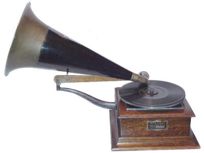
early Victor phonographs used an external horn. External-horn Victors varied considerably in design
detail in early years, evolving in sophistication as more was learned about effective transfer of vibro-acoustic energy from the disc to the surrounding room. The earliest designs had an integral horn and soundbox structure
(photo at left). In
these models, the horn's neck was attached directly to the soundbox housing, and
the entire horn assembly moved along with the needle as the record was played. Some of the horn's weight was supported at a pivot point, allowing the soundbox/horn assembly to
freely follow the record grooves. However, along with the needle, the
record groove also had to pull-along half of the mass of the entire playback system (soundbox
and some of the horn's weight). This mass-loading resulted in loss of frequency response, and caused premature record wear. To increase the audio
volume, the horns became larger and larger, and the need to counterbalance the horn's
increasing weight became a serious problem. The weight of very large horns could
wear-out a record after only a few plays!
All
early Victor phonographs used an external horn. External-horn Victors varied considerably in design
detail in early years, evolving in sophistication as more was learned about effective transfer of vibro-acoustic energy from the disc to the surrounding room. The earliest designs had an integral horn and soundbox structure
(photo at left). In
these models, the horn's neck was attached directly to the soundbox housing, and
the entire horn assembly moved along with the needle as the record was played. Some of the horn's weight was supported at a pivot point, allowing the soundbox/horn assembly to
freely follow the record grooves. However, along with the needle, the
record groove also had to pull-along half of the mass of the entire playback system (soundbox
and some of the horn's weight). This mass-loading resulted in loss of frequency response, and caused premature record wear. To increase the audio
volume, the horns became larger and larger, and the need to counterbalance the horn's
increasing weight became a serious problem. The weight of very large horns could
wear-out a record after only a few plays!
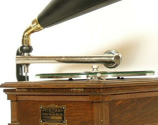 Eventually, a "rigid" tonearm design was developed in which only the tonearm and soundbox moved along the record while the horn remained stationary
(photo at right). This
was accomplished by using a simple pivot joint between the tonearm and the horn itself. This design served to decouple the mass of the horn from
the soundbox and tonearm. Subsequent improvements to tonearms resulted in a gradually expanding diameter (taper)
from soundbox to horn, which further improved the system efficiency
by providing a better acoustical impedance match. Soundboxes also evolved to improve their performance. These topics
are discussed in depth in the technical articles.
Eventually, a "rigid" tonearm design was developed in which only the tonearm and soundbox moved along the record while the horn remained stationary
(photo at right). This
was accomplished by using a simple pivot joint between the tonearm and the horn itself. This design served to decouple the mass of the horn from
the soundbox and tonearm. Subsequent improvements to tonearms resulted in a gradually expanding diameter (taper)
from soundbox to horn, which further improved the system efficiency
by providing a better acoustical impedance match. Soundboxes also evolved to improve their performance. These topics
are discussed in depth in the technical articles.
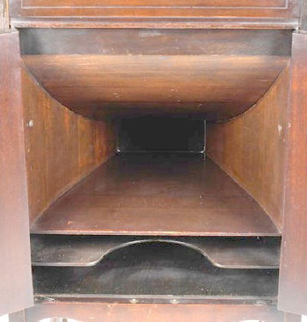
The introduction of the 1906 "Victrola" revolutionized
the fundamental phonograph design simply by inverting the route of the
sound waves downward to the horn, which was now mounted inside the cabinet. This resulted in a much less intrusive piece of furniture, and the use of integral doors in front of the horn's outlet allowed the listener
to adjust the playback volume. The internal horn was smaller and was "squared off", which resulted in reduced volume when compared to the external horn models, but
the public preferred the appearance and convenience of these newer machines, and they soon outsold their earlier
external horn counterparts. Soundbox improvements continued to be made though
the 'teens,
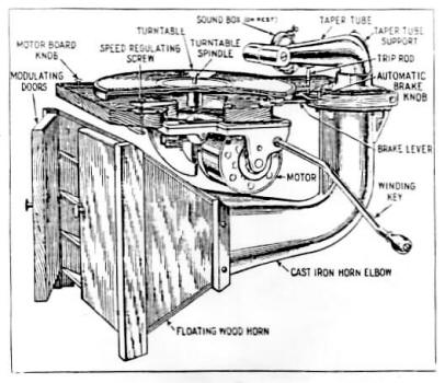
but the basic design configurations remained the same. A diagram of the
fundamental components and layout of a typical Victrola are shown below.
Victrola sales boomed from 1906 through 1921, and by that time, almost every middle and upper-class home in the USA had a phonograph in the parlor. The Victrola internal-horn concept proved to be a stunning success. But while numerous trial-and-error incremental improvements to phonograph designs and recording processes had been made over the years, the overall "canned" sound quality was little changed from the time the Victrola was first introduced in 1906. When radio sets became affordable in the mid-1920's, the electronically-amplified sound from these systems was vastly superior to that of acoustic phonographs, and Victrola sales began to wane. Victor resisted making changes to their "tried-and-true" phonograph products, and only when it became obvious that consumers preferred buying radios to the old-style phonographs, did the company begin to offer Victrolas with an empty space in the cabinet for the installation of an aftermarket radio set. But this did not solve the problem. By the summer of 1925, Victrola sales had tanked so badly that The Victor Talking Machine Company was rapidly approaching insolvency. The company had waited far too long to make improvements to their products, and the public was no longer interested in buying Victrolas. Victor and its dealers were then forced to dump their massive unsold inventory of nearly 100,000 Victrolas at half-price, resulting in huge financial losses. In a panic-development program (with support from Western Electric), Victor produced the Orthophonic line of advanced acoustic phonographs. These machines were launched in November of 1925, and provided an incredible improvement in sound quality when compared to the Victrolas of just a year earlier. The Orthophonics used the same fundamental acoustic phonograph concepts as before, but many of the critical design parameters were optimized using advanced mathematical equations that had been developed for communication purposes during World War One. An increased compliance (responsiveness) of the stylus was achieved through use of a ball-bearing needle support system in the soundbox, with magnets added to improve alignment and assure stability. This reduced record wear and improved low-frequency response. In addition, an increase in the stiffness of the soundbox diaphragm, now made of pleated aluminum, improved the overall performance characteristics and reduced the non-linearities that were inherently present in the old mica diaphragm design, which had contributed to distortion. But most importantly, acoustic impedance-matching equations were applied to the horn designs, greatly increasing both the listening volume and widening the frequency response of the phonograph. These were called "exponential horns", and the resultant sound quality was markedly improved. A diagram of the largest Orthophonic phonograph is presented below left, showing the complexity of the internal geometry of the "folded" (re-entrant) exponential horn. This horn configuration allowed the sound waves to gradually transition from the small tonearm opening to the listening room (using an optimized rate of expansion), which resulted in more acoustic energy being transmitted into the room, rather than being reflected back into the tonearm as was the case in earlier designs. The sound-path was wrapped back and forth inside the horn structure to control the rate of expansion over an equivalent distance of over 6 feet, but still allowing the overall package to fit inside a reasonable 22" deep cabinet. Many of the higher-priced Orthophonic machines used this complex folded-horn design. Lower-priced models used a direct-path semi-exponential horn (below right) which, while mathematically-shaped to provide some degree of optimized soundwave matching to the room, did not provide the same efficiency and resultant low frequency response as did the more complex and expensive horns.
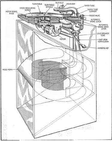
Listen to the difference! Click on the pictures above to hear the playback performance of each type of exponential horn. The microphones were placed 6 feet in front of the horn, playing the same record and using the same tonearm and soundbox system. No gain or equalization adjustments have been made. The larger folded horn provides vastly superior bass response, as well as a greater overall volume. This would have been what buyers would have experienced in the Victor showrooms in 1925, when comparing different Orthophonic models. The large 're-entrant' exponential Credenza horn on the left, and the small semi-exponential horn on the right.
A detailed analysis and resulting
comparative performance of many of these evolutionary designs is discussed in the
Technical Articles Section. The key point to
remember, however, is that the basic overall principal of operation of the
acoustic phonograph remained the
same from the earliest models until electrical pickup came into common use in
the late 1920's. Vibration induced from the moving record is converted into
sound waves in the tonearm, and is then transferred to the listening room via
a horn.
In parallel with the development of the Orthophonic Horn, Victor also began to investigate the possibilities of 'electronic recording and playback'. Western Electric had pioneered the development of advanced audio technologies after World War 1, and by the mid-20's, it became practical to make electrically amplified audio recordings. Prior to this, singers or bands had to jam themselves in front of a 'recording horn' to make records. The advent of efficient microphones, electronic (tube) amplifiers, and electrically-driven speakers changed the recording industry forever. The sound quality on records was vastly improved, and the amount of distortion and noise was significantly reduced. Victor began making electrical recordings during the summer of 1924, and within a year, the microphone had completely replaced the acoustic recording horn in virtually all studios across the country. These early electrical recording systems were very costly, but the benefits in fidelity more than justified the increased expenditures.
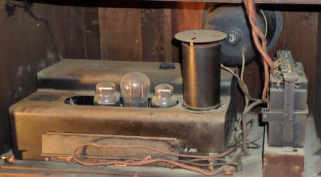 The
acceptance of "home playback" systems using electronic components
is quite another story. Early tube amplifiers and speakers were horrifically
expensive when first introduced in the mid-1920's. A simple 5-watt audio
amplifier system (picture on left) weighed about 50 lbs., and cost upwards of
$200.00, (about $3,000.00 in today's money), so it was not commonly found in
most homes at that time. These early systems were also not very reliable,
required considerable maintenance, and generated a lot of heat inside the
cabinet. But the amazing growth of home radio in those early years
began to drive-down the high cost of electronic parts. Prices of tubes,
transformers and other components fell dramatically as more and more were
being made by radio companies and their suppliers. The same can be said of
speakers during those years. Early speakers were not very efficient and produced
a great deal of distortion. They relied on magnets (usually electrically-induced) to function, but
many of these early electromagnets were not adequate to produce the necessary magnetic fields
for good sound reproduction at a reasonable cost. But these problems were
overcome as well through continuing research and development, as well as
via partnering with the manufacturers of radios and other electronic
equipment.
The
acceptance of "home playback" systems using electronic components
is quite another story. Early tube amplifiers and speakers were horrifically
expensive when first introduced in the mid-1920's. A simple 5-watt audio
amplifier system (picture on left) weighed about 50 lbs., and cost upwards of
$200.00, (about $3,000.00 in today's money), so it was not commonly found in
most homes at that time. These early systems were also not very reliable,
required considerable maintenance, and generated a lot of heat inside the
cabinet. But the amazing growth of home radio in those early years
began to drive-down the high cost of electronic parts. Prices of tubes,
transformers and other components fell dramatically as more and more were
being made by radio companies and their suppliers. The same can be said of
speakers during those years. Early speakers were not very efficient and produced
a great deal of distortion. They relied on magnets (usually electrically-induced) to function, but
many of these early electromagnets were not adequate to produce the necessary magnetic fields
for good sound reproduction at a reasonable cost. But these problems were
overcome as well through continuing research and development, as well as
via partnering with the manufacturers of radios and other electronic
equipment.
The early adopters of electronic home playback systems paid a pretty penny for this finicky technology, which would become totally obsolete within a short time. That $200.00 5-watt amplifier would be replaced by a 10-watt version that sold for less than half the price within 2 years. It was not uncommon for complete Victor electronic radio/phono sets to cost upwards of $1,000.00 in 1925; in a couple years it could be replaced by a far superior set costing less than half that much money. Rapid obsolesce was truly a way of life in the 1920's, which included cars, radios, and virtually everything else. The pace of technological development was nothing short of remarkable.
By 1929, electronic systems had dropped in price to the point where they became cheaper to produce than large acoustic horns. This sounded the 'death knell' for the acoustic Victrola. By the early 1930's, only small portable machines and cheap table-top models used horns, and virtually everything else (radios, phonos, intercoms, etc.) became exclusively electronic. The era of electronic audio reproduction had taken hold. Victor was sold to RCA in 1929, and radios became king, while phonographs tended to become an ancillary feature in home audio. But by this time, The Depression had appeared, and consumers were not buying much of anything. This was to remain the case until the late 1930's, when 'spending money' became more readily available to the consumer.
The basic reproduction process is as follows:
The stylus tracks the grooves in the record which contain the acoustical signal. This signal source consists of a lateral displacement of the groove itself. As the
record spins and the stylus tracks the groove, this lateral movement is translated into stylus motion (vibration). This motion contains both the frequency and
amplitude information of the audio signal (picture at right). Many different stylus designs were available over the years, with varying degrees of thickness and shapes.
As a rule a "loud tone" stylus was of a thicker and heavier design than was a "soft tone" stylus.
A thick stylus has higher stiffness, and does a better job of coupling of high frequency vibrations into the soundbox, resulting in a subjectively higher volume.
The stylus is held in place by the thumbscrew, which serves to hold the stylus tightly  in the stylus bar assembly (diagram
at left). The lateral vibration of the stylus is coupled to the center of the diaphragm, which
moves the column of air in the tonearm. The stylus bar assembly serves to
couple the vibrations from the stylus itself to the soundbox diaphragm. Note that a significant mechanical advantage is provided through this system. The relatively
small motions of the stylus itself are increased significantly due to the leverage across the pivot point (the overall magnitude of this advantage is dependent on
the type of soundbox and the frequency content of the signal), resulting in a much larger displacement at the center of the diaphragm. This is a variation of the
simple mechanical lever concept. The support springs serve to keep the leverage mechanism in place and yet allow sufficient dynamic motion to be coupled
from stylus to diaphragm. Many other variations of this basic design appear in
early phonographs.
in the stylus bar assembly (diagram
at left). The lateral vibration of the stylus is coupled to the center of the diaphragm, which
moves the column of air in the tonearm. The stylus bar assembly serves to
couple the vibrations from the stylus itself to the soundbox diaphragm. Note that a significant mechanical advantage is provided through this system. The relatively
small motions of the stylus itself are increased significantly due to the leverage across the pivot point (the overall magnitude of this advantage is dependent on
the type of soundbox and the frequency content of the signal), resulting in a much larger displacement at the center of the diaphragm. This is a variation of the
simple mechanical lever concept. The support springs serve to keep the leverage mechanism in place and yet allow sufficient dynamic motion to be coupled
from stylus to diaphragm. Many other variations of this basic design appear in
early phonographs.
The diaphragm's vibration serves to convert the mechanical energy (vibration) into acoustic energy. It is essentially a membrane-type "piston" which excites
the column of air in the tonearm itself. This oscillating column of air in the tonearm is called a
"plane progressive acoustic wave". However, since the diaphragm itself is
highly flexible and is held firmly in place by the gasket at its edges, the
center will vibrate a great deal and the edges will move very little. Thus,
the motion is not equally distributed over the entire diaphragm, resulting in some degree of distortion in the sound wave. The greater the distortion, the poorer
the reproduced sound.
The sound wave moves through the tonearm and into the horn, which serves to match the acoustic impedance of the tonearm to the listening room. The
concepts of acoustic impedance and the utilization of tapered structures (tonearms and horns) are covered in detail in the
technical articles. Suffice it to say
that different horn and tonearm tapers have different impedances, resulting in different efficiencies. The lower the efficiency, the less the sound volume
produced in the room, and the poorer the low frequency response. Many types of horn designs and materials have been used over the years, resulting in a great
variation of sound qualities and volumes.
One of the key problems in the design of acoustic phonographs was in designing a "smooth-flow" tonearm. Ideally, the tonearm and horn should consist of one
continuous, constant and unbending taper from soundbox to the end of the horn
itself. However, the practicalities of making a phonograph both reasonable
in size and convenient to use mandated that certain compromises be made. The
sharp bends at the connection between the tonearm and the horn, as well as
the U-shaped gooseneck at the soundbox tube all contribute to reduced
acoustic efficiency and added distortion.
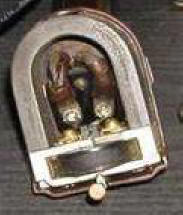 Electronic
reproduction in phonographs of the 1920's used the same basic principle of
deriving its source from the lateral movement of the needle on a record;
however instead of using a mica diaphragm to convert the vibration into a
sound wave, that vibrational energy was converted into an electrical current via a
"magnetic pickup". Early magnetic pickups used actual horseshoe magnets to
create a "magnetic field" within the pickup structure (picture at left). The
vibrating needle's motion was mechanically connected to a small coil which
was surrounded
Electronic
reproduction in phonographs of the 1920's used the same basic principle of
deriving its source from the lateral movement of the needle on a record;
however instead of using a mica diaphragm to convert the vibration into a
sound wave, that vibrational energy was converted into an electrical current via a
"magnetic pickup". Early magnetic pickups used actual horseshoe magnets to
create a "magnetic field" within the pickup structure (picture at left). The
vibrating needle's motion was mechanically connected to a small coil which
was surrounded 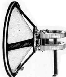 by the induced magnetic field. As the coil moved with the
needle vibration, a small amount of proportional electrical energy was
developed within it, which was then carried by wires through the tonearm to
an electronic amplifier. There were no more concerns about distortion and
signal loss caused by acoustic waves
flowing through curving tonearms and horns; the entire sound transmission and
reproduction process became electrical. To be sure, electrical reproduction
had its own set of design problems as well, which will be discussed below;
but it was vastly superior to the acoustic process.
by the induced magnetic field. As the coil moved with the
needle vibration, a small amount of proportional electrical energy was
developed within it, which was then carried by wires through the tonearm to
an electronic amplifier. There were no more concerns about distortion and
signal loss caused by acoustic waves
flowing through curving tonearms and horns; the entire sound transmission and
reproduction process became electrical. To be sure, electrical reproduction
had its own set of design problems as well, which will be discussed below;
but it was vastly superior to the acoustic process.
The incoming signal from the pickup was then "magnified" (the correct term is amplified), e.g. converted into a much stronger electrical signal at the amplifier's output. This enhanced electrical signal could then be reproduced via a speaker (or electromagnetic driver), wherein the function of the magnetic pickup was reversed. Within the speaker, the strong electrical output from the amplifier was connected to a coil, which was surrounded by a magnetic field. The coil would then vibrate within the field in response to the electrical signal. If a large paper cone or other lightweight structure was connected to the vibrating coil, the cone would also vibrate...producing an audio sound (right).
The earliest electronic playback systems were quite crude by today's standards. Lots of low frequency "hum" was present, and early speakers had a very limited frequency response and volume. An occasional burst of unwanted energy (BRAAATTTTTT!!!) would often interrupt your music, usually coming from a nearby light switch being flipped or from a neighbor's radio generating interference in the local area. However, electronic audio phonographs were immediately recognized as being far superior to the acoustic phonographs. Volume was far better, the sound quality was clearer and the volume control allowed you to play music softly or as loud as your system would allow, without the need for opening and closing doors. As time progressed and designs were improved, the sound quality approached levels that were never imagined just a few years before.
The "Technical Articles"
Section will discuss the various designs and configurations of these components, and will detail the technical development of the
designs as well as to show vibro-acoustic data taken from a variety of machines. The effects of various stylus, diaphragm, horn and tonearm designs
will be detailed, along with supporting data. Readers who are unfamiliar with acoustical engineering concepts and terms are encouraged to read the
"Introduction to Vibro Acoustics" page under the heading "Technical
Articles on the Victrola Phonograph".