
The Victor-Victrola Page

Fundamentals of Acoustic Horns
Author: Paul C. Edie
Originally published in the Michigan Antique Phonograph Society Journal, 1998
Of all the phonograph topics that have been discussed by collectors and hobbyists, the one that causes the most confusion and misinterpretation is the physics
of the phonograph horn. This article will attempt to present the basics of how a horn works; subsequent articles will cover the concept of acoustic impedance
and performance effects of different horn designs. It is essential the reader be familiar with the concepts covered in An Introduction to
Vibro-Acoustics prior to tackling this topic.
A phonograph's horn is much more than just a structure to "point" the soundwaves in a certain direction, although if you read some of the available literature,
one could easily assume that is its primary purpose. Anyone who has ever listened to an acoustic phonograph with the horn disconnected knows that both the
volume and the fidelity of the playback is greatly reduced, no matter if the listener is standing directly in front of the tonearm opening or standing behind it. Yes,
the horn does provide some directivity to the sound, but simply stated, its primary purpose is to match the characteristics of the sound wave from the narrow
tonearm into the large spatial area of the listening room.. Likewise, the tapering tonearm is itself a miniature horn; it serves to better match the sound pressure
wave created by the soundbox diaphragm to the opening of the horn itself.
This sounds more complex than it really is. When a sound wave propagates along inside of a tube (tonearm), there really are only two key characteristics
needed to explain the nature of the wave. One is the amount of pressure variation that the wave creates at any given point (usually abbreviated as "P") and the
other is the speed at which the individual molecules vibrate (usually abbreviated as "U"). Note that U refers to the moving speed of the molecules as they
vibrate back and forth, not the speed of the soundwave itself through the tube, which in air, is fixed at 944 feet/second. Think of this as a slinky toy moving
down the stairs. The individual coils of the slinky are compressing and expanding very rapidly, almost faster than the eye can follow, and yet the slinky
progresses down the stairs at a fairly low rate of speed. This same analogy is applicable to the movement of the sound wave; the wave moves relatively slowly
but the vibrational speed of the molecules is much faster.
For this example, let's assume a simple case wherein the soundbox diaphragm is vibrating at a constant level and that the tonearm tube is straight and
un-tapered (Figure 1). In this example, each molecule is vibrating back and forth about it's center point. As each one vibrates, it bumps into adjoining
molecules, compressing them and then decompressing them as they bounce back. The molecules themselves don't move down the tonearm, but rather bounce
back and forth about their central points. However, as time progresses, the pressure wave caused by the compressing and decompressing molecules "moves"
down the tonearm. For the instantaneous moment in time shown in Figure 1, the high and low pressure (compression and decompression) points are shown for
the moving pressure wave. The amount of pressure variation (Pmax-Pmin) in the tonearm tube is a function of the
amount of excitation at the source (in this case the amount the reproducer diaphragm is moving) and the diameter of the tonearm tube. Since pressure is defined as force/area, as long as the diameter of the
tube is unchanged, the cross sectional area remains the same, and the pressure variation is constant. The vibrational velocity of the individual molecules also
remains relatively constant within the confines of the tonearm. The transfer of vibrational energy from molecule-to-molecule is stable since the size of the
tonearm is constant; vibrating molecules are bumping against the same number of adjoining molecules as the wave moves down the tonearm.
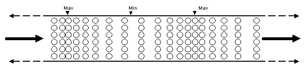
Figure 1. Representation of a pressure wave movement through a constant diameter tube. Each molecule (represented by the circles) is vibrating back and forth, bumping into
adjoining molecules in a "chain reaction" motion. This causes a pressure wave of molecular compression and decompression which moves along the tube, even though the
molecules themselves simply vibrate about their own center points. The motion of the pressure wave is shown by the arrows and the pressure minima and maxima are indicated
above the tube.
However, assume that the conditions of Figure 2 exist wherein the tube abruptly ends and opens into a room. When the soundwave exits the confines of the tube, both soundwave characteristics (P and U) change dramatically. The pressure drops significantly, since the area of the room is much larger than the area of the tube. In addition, the air molecules at the end of the tube, which are vibrating and transferring the acoustic energy, suddenly come into contact with a huge number of molecules in the listening room. The relatively small number of vibrating molecules at the opening suddenly have to "push" against an entire room of molecules, which causes an abrupt change in the vibrational velocity of the molecules at this transition point. This results in a large part of the vibrational energy of the soundwave being reflected back into the tonearm, and not into the room. When this occurs, it tends to "cancel" and distort the forward moving wave that is attempting to move up the tube and out into the room. Thus, in the room, we hear a greatly decreased volume and poor fidelity
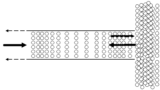
Figure 2. Representation of a pressure wave movement through an abrupt change of area. In this instance, the pressure wave suddenly has to push against a huge increase in
mass due to all the molecules in the room. As a result, most of the pressure is reflected back into the tube.
An excellent analogy to this situation is the two steel balls as shown in Figure 3. The smaller ball (weighing 1 pound) is moving toward the larger ball at a speed
of 10 feet/second and the larger ball (weighing 100 lbs) is at rest. As soon as the small ball strikes the larger one, it is unable to transfer much energy to move
the larger ball, and ends up bouncing off and reversing direction. Using Newton's equations (shown at the bottom of Figure 3), we can calculate the velocity of
both balls right after impact as shown in Figure 3c. The same situation occurs with a soundwave
traveling down an un-tapered tube; the mass of all the air
molecules in the listening room is so much greater than the mass of the molecules vibrating at the tube opening, that most of the sound energy is sent back into
the tube, where it actually "fights" and reduces the power of the soundwaves which are trying to move forward. Thus, the amount of sound energy is greatly
reduced when the transition from tube to room is so abrupt. And since the magnitude of molecular vibration for low frequency sounds is much greater than that
of high frequency sounds, it stands to reason that low frequencies are most reduced when the transition is abrupt. Without a horn, we hear very little bass and
very low amplitude distorted sound.
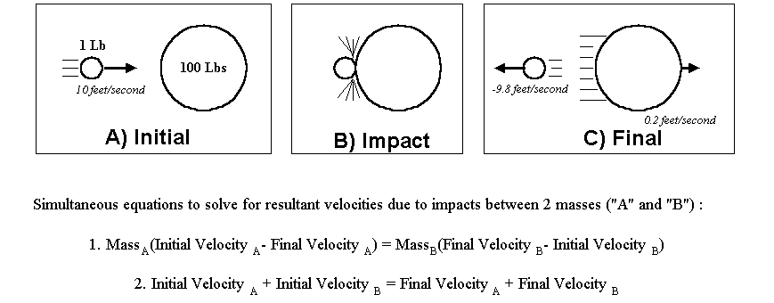
Figure 3. The effect of a collision between a ball of small mass and a ball of large mass.
When the transition is from tube to room is gradual (as found in a horn or tapered tonearm), the result is that more of the energy is transferred out of the tube and horn and into the listening room. Instead of an abrupt change in the mass of the molecules from the narrow tonearm into the listening room, the horn's taper allows the molecule-to-molecule impacts to slowly adapt to the huge number of molecules in the listening room. While there will still be some reflection of the soundwave back into the horn at it's opening (since there still is a large number of molecules in the listening room relative to the number at the opening of the horn), the match in molecular mass from the opening to listening room is much better when the horn is used. The pressure wave can now transfer its energy gradually to a larger and larger number of adjoining molecules at each point along the horn until it exits the horn (Figure 4). Obviously there are many more molecules at the horn's opening which can work against those in the listening room than there was with the un-tapered tube shown as shown in Figure 2.
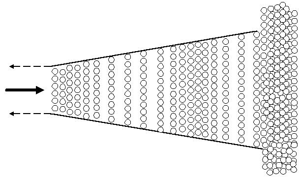
Figure 4. The effect of the horn allows the molecules to transfer their vibrational energy gradually to ever-increasing numbers of adjoining molecules, which results in more
sound energy being delivered into the listening room, and less energy being reflected back into the horn. The example shown here is a horn with a rather gradual and short
taper, but the overall concept of increasing numbers of molecules is clearly seen.
The "rolling ball" analogy to a horn is shown in Figure 5. The 1 pound smaller ball is moving at 10 feet/second (as it was in the previous example), and the
larger 100 pound ball is still at rest. However, we have now added an intermediate ball, weighing 10 pounds (also at rest) between them. Using Newton's
equations, the results can be seen as the balls collide and move. In the end, the 100 pound ball now moves forward at a slightly greater speed than it did in the
previous example, simply because there is a "transition" ball in between the small and large balls. The 1 pound ball also bounces back at a slightly slower speed
than before. In the case of the phonograph horn, this means that less sound energy is reflected back into the tonearm, and the amount of interference is
reduced.
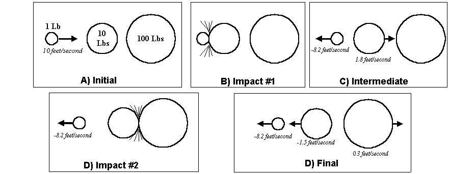
Figure 5. Adding an intermediate ball between the two actually increases the final velocity of the 100 lb. ball by 0.1 ft/second.
Taking the concept a step further is demonstrated in Figure 6. As we continue to add intermediate (gradually increasing mass) balls between the 1 pound and 100 pound end balls, the more effectively the energy is transferred to the 100 pound ball (it moves faster), and the 1 pound ball bounces back at an even slower velocity. The same principal applies to the acoustic horn. The more gradual and controlled the taper, the more energy is transferred into the listening room.
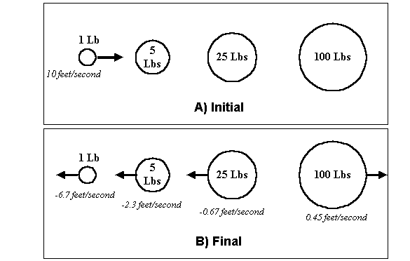
Figure 6. The addition of two intermediate balls between the 1 lb. and the 100 lb. balls serves to increase the final velocity of the heavy ball by 125% (only the beginning and
ending conditions are shown here; the balls are assumed to have sequentially collided and bounced back as shown in Figure 5). The more gradual the energy transfer from
mass-to-mass, the more energy is ultimately transferred to the large ball.
Of course, these analogies are only rough approximations of the complex events that occur when a sound wave travels through a tonearm and horn, but the
key factor to remember is that the horn's primary function is to slowly transition the transfer of vibrational energy from layers of molecules which are gradually
increasing in number until the wave exits the horn into the listening room. The fact that both the tonearm and horn
are tapered in most phonographs manufactured after 1905 means that an even more gradual transition occurs as the soundwave travels from reproducer to room, which greatly improves the
overall efficiency (volume) and low frequency response.
During World War 1, a great deal of work was done to mathematically estimate the most efficient transfer of energy
across boundaries. Of course, a side benefit to this work was the
development of a more efficient acoustic horn. Several factors must be considered in making this calculations, for each time two molecules collide, some amount of energy is lost in the collision, and thus, a horn of infinite taper
would eventually cause the soundwave to "run out of gas" before it could reach the end. The calculations in horn design must take into account the most
efficient molecule-to-molecule transition rate as well as to assure that the horn is not so long as to cause the soundwave to fade out. This would be equivalent
to computing the most efficient number and size of intermediate balls in the examples of Figures 5 and 6 such that the 100 lb. ball travels the fastest. The results
of these efforts were the equations which drove the design of the Orthophonic machines of 1925. The horn taper was optimized, resulting in much less low
frequency energy being reflected back into the horn, and thus greatly improving bass response. This topic, along with a host of other improvements in these
machines will be discussed in upcoming articles.
Every tubular cavity (tonearm and/or horn) has a distinct resonant or natural frequency, which tends to "amplify" certain groups of tones, just like the effect one
can get when blowing across a pop bottle. Left unchecked, resonant effects can totally dominate the sound we hear, and result in very annoying sound quality
wherein certain notes are played at very loud levels and others are barely audible . The effects of resonance are highly complex and beyond the scope of this
article, but the use of tapered tubes and horns tends to broaden and reduce the resonant characteristics and reduce the sensitivity of the phonograph to
over-respond to specific frequencies. This additional benefit of tapered tonearms will be covered in future articles.
Finally, the bends and curves that occur in a tonearm's gooseneck and in horn elbows also reduce acoustic efficiency. These features tend to cause some
energy from the soundwaves to strike the internal walls at the bends, and some portion of the wave is reflected backwards, reducing the strength of the
forward moving sound wave. When you listen to a Victor V compared to a Victrola XVI, the "V" has a better
sound not only because the horn is larger (and with a better taper), but also because the bends in the elbow joints are less severe, resulting in fewer internal reflections. These bends and curves also give rise
to soundwaves which may no longer travel "straight" down the tonearm tubes or horns, but instead bounce off the inside diameter in a zig-zag fashion as they
exit into the listening room. High frequency sound reflects from hard surfaces similarly to the way that light reflects from a mirror; if the sound wave is no longer
aimed straight down the tube, it bounces back and forth along the inner diameter as it moves along. Some of the hobby literature on acoustic phonographs
claims that this zig-zagging phenomena is the main reason that horn structures increase the
overall volume of sound. According
to these texts, the waves bounce back and forth (zig-zag) fewer times as they
exit a tapered horn than they would in a straight tube, and thus arrive stronger
to our ears (NOT!!!). Low and medium frequency sound waves certainly reflect to
some extent within a horn structure, but the internal bouncing effect has virtually nothing to do with the increased sound radiation efficiency
(e.g sound volume) of phonograph horns. The primary reason for the louder volume
is due to the horn's improved impedance matching with the surrounding room as
discussed above. However there is one important outcome from the high frequency zig-zag wave phenomena. Since it is
mostly the high frequencies that are zig-zagging, higher
pitched sounds will strike and bounce off the phonograph's horn structure itself many times as they travel to the listener. If the horn is made of wood, it's rougher inner
surface will diffuse much of the reflected high frequency energy in all directions, reducing its strength. A smooth metal horn will efficiently reflect most of the
high frequency energy. These effects give us the characteristic wood and metal horn sound quality that we hear, which is nothing more than the amount of high
frequency content in the sound. A metal horn simply has greater high frequency content.